
Roll forming is one of the oldest but still misunderstood metal forming processes. And its capabilities continue to grow. Getty Images
The following article is partly based on the “Reason for Roll Forming” prepared by Formtek Inc. Senior Application Engineer Brian Rodgers for the FABTECH conference.
The basic concept behind roll forming can be traced back to Leonardo da Vinci. The first continuous roll forming production line can be traced back to the 1910s. However, even after so long, many people still don’t know what roll forming is. It is the main product of certain industries such as the automobile, aerospace and metal construction industries, but it is still brand new to many centuries-old metal forming technologies.
Understanding what roll forming can and cannot do can open the door to a large number of metal forming possibilities. In most cases, it all starts with the contours of continuous parts with high-volume requirements.
Even those who know roll forming will continue to be surprised by what might happen. Nowadays, some manufacturers have developed proprietary methods to push the limits of roll forming by die-casting metal to produce part contours that look like extrusions, rather than being made from a roll of sheet metal. Others have found ways to form shapes with discontinuous cross-sections, such as C-shaped channels that “squeeze in” like a bow tie.
But most traditional roll forming applications still require continuous cross-sections or contours. It can be a simple C-shaped or U-shaped channel, or an extremely complex irregular shape. The part can be straight, curved, or even twisted into a spiral. But in all these geometric changes, the part contour is continuous.
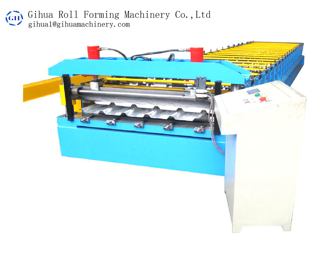
To understand why a basic understanding of roll forming methods is required (see Figure 1 and Figure 2). The material comes out of the coil or blank by a precision straightener (if required by the application), and then enters the first frame of the roll forming line. The upper and lower roller tools on each stand perform a certain amount of forming, together forming the so-called roll forming flower, which is an illustration of how to roll the part into the contour of the finished product.
When the metal strip passes through, the upper and lower roller tools on each frame form a specific number of contours, depending on the metal thickness, grade, material yield and tensile strength, part geometry, feed rate and other variables . Like stamping and bending forming, roll forming must deal with springback. The metal is formed as it is squeezed through the first set of rolls, and then slightly relaxes (due to springback) before entering the next set of rolls or forming passes. The next stop forms the next “petal” part of the flower pattern, taking into account the rebound of the previous pass. Therefore, the process will continue until it reaches the correction station or sweeping block, eliminating or causing bending before it is completed or cut to a certain length at the end of the production line (see Figure 3). The resulting parts can be straight, curved, and even form spiral patterns.
Of course, the roll forming production line contains various rolls, but they also have at least one mold, but usually there are multiple molds. Each continuous production line has a cutting die, which can cut the final roll-formed part to a certain length (see Figure 4). Some blank roll forming lines are manually fed, but others have preform molds that can be cut to length before feeding the strip into the roll forming line.
Holes and other cuts for other molds on the line. When it occurs before the metal is formed, it is called pre-grooving or pre-perforation. When the punching operation occurs after or between the forming station, it is called the middle notch-sometimes this is a necessary step, for example, punching a hole before forming can cause undesirable stretching.
Slotting and blanking molds can remain stationary and fixed on plungers and backing plates, or they can travel along tracks mounted on the base. The entire hydraulic or pneumatic press assembly, sometimes just the mold, moves linearly (see Figure 5). ). These flying molds increase the flexibility of the roll forming line.
Some production lines incorporate special molds to form embossing, slots, labels, shutters and other value-added functions. In applications that require high speeds, rotating molds can be used. As the mold rotates, cuts and templates are created at speeds in excess of 100 feet per minute.
If you see roll-formed parts that are a bit welded along the seam-and there is no secondary spot welding station on the floor-most likely they were placed there by a process called rotary resistance spot welding, which will The material is clamped between two copper electrode wheels and allows welding while the material is moving. This process is used for bumper beams and door frames in the automotive industry. In fact, rotary spot welding has been the first choice for bumper beams for many years. Today, many roll-type production lines use high-frequency welders to produce custom welded pipes (see Figure 6).
Like any forming process, roll forming creates stress in the part, which can cause some kind of deformation. This includes so-called terminal flares. Without compensation, all roll-formed parts will appear toe at the front edge of the part and spread out at the rear edge. This phenomenon usually occurs within the first and last 6 inches of the part length. The root cause is related to the elastic properties of metal, similar to springback in stamping and bending forming.
To make up for this, the roller production line is equipped with an anti-flaring device including a series of sliders, rollers and spindles. These units over-bend parts of the part, causing it to spring back to the desired shape.
One of the biggest advantages of roll forming is its ability to form a variety of materials, including high-strength/low-alloy (HSLA) steel. Engineers can control the roll pressure to adapt to the bending stress by adjusting the inside and outside of the rolling mill stand. They can also reduce the degree of bending of each rolling mill stand. For example, an engineer might decide to bend a part to 5 degrees between five roller racks, instead of bending the part 25 degrees on a tool rack.
Additional roller tables can help solve “material memory”, but these passes need to be placed strategically. The geometry of the part sometimes requires certain roller stands to process the material, but not others. Adding brackets can make the world meaningful, but they need to be placed where they are most useful, which may vary from application to application.
In any case, adjusting the number of brackets (and the tools on each bracket) provides engineers with another “turning knob” to adjust and refine the process. All these “adjustable knobs” are one of the reasons why roll forming can make so many different types of materials into so many shapes.
Sometimes, roll forming prevents spirals and other shapes from being manufactured in any other way. But when the decision to roll forming is based solely on the part geometry, it is usually related to the part size.
In theory, roll forming has no limit on the length of the part. The only real limitation is practical: that is, when a part emerges from the production line, how do you deal with it. Sometimes chutes are used to handle extremely small, short parts. The slag emptying system under the mold can actually become a partial emptying system; that is, the slug is a part.
At the other extreme, the parts can be very long. The punching machine has a bed size limit, while the bending bed can only have this length. But even the most compact roll forming production line does not have a theoretical part length limit. The only limiting factor is the space and ability to manipulate molded parts.
Regarding width, the only limiting factor is usually the width of the coil. As we all know, some roll-type production lines can process workpieces of various widths (see Figure 7). These include duplex lines formed only near the edges of the material, which can be in and out to accommodate different widths without the need to change tools.
Figure 1 Roll profile is formed by a complete set of rolling tools. Remove the roll holder to illustrate the transition of the workpiece.
The rapid reorientation of duplex production lines illustrates the flexibility of some roll forming lines, especially when processing parts with certain attributes. Some roller production lines in the bleachers and seating industries can produce different parts one after another. These parts share the same profile, but have different lengths and hole patterns. All of these are installed and shipped in the exact order required by the installer on the job site.
The rapid conversion of roll forming can be done in a variety of ways. For example, a special production line can be built to roll a small number of different parts, each using a specific rolling mill stand. This only applies to certain types of part geometries and certain tolerance requirements-essentially, the roll forming line is tailored to the needs of a specific, usually high-volume part combination-but it is under specific circumstances A choice.
The new programmable controller can change the punching mode, part length and other properties. For the different modes of each part, the conversion may not be immediate or instant, but it may happen within a few minutes.
Another quick replacement option is to use the raft line (see Figure 8), where the entire set of upper tools are preset in the raft and can be lifted into place. The small roll forming production line can be completely composed of a raft that can be replaced as needed. This technology introduces rapid conversion to a wider product portfolio. Raft conversions are not instant, but they are faster than traditional manual conversions, in which operators can spend hours manually replacing and aligning tools.
The labor cost of roll forming usually accounts for 3% to 15% of the total work cost. Why is it wide? This is largely due to the difference in the level of automation available and the product mix and complexity of the roll forming line.
Roller production lines that require manual conversion may require a lot of labor, depending on the number of conversions required by the production line. On the other hand, some companies may have only one employee to manage three separate production lines. The controller manages most of the conversion, and the parts are automatically unloaded into the Kanban box. An employee may spend most of his time monitoring the process and preparing a new coil for the next job. In some high-volume environments, the roll forming machine may not have an operator at all.
To further reduce the amount of labor, automatic calibration helps to reduce some of the black magic of roller settings, and in many cases can actually be adjusted in real time. Just as bending machines provide real-time angle measurement, roll forming production lines now provide real-time adjustments to account for material variability and keep the final part geometry within the tolerance window.
After setting, roll forming always provides a high degree of consistency from part to part. The standard profile tolerance is ±0.030 inches and the angle is ±2 degrees. The torsion tolerance can be less than 0.120 inches and more than 40 inches; the camber tolerance can be within 0.040 inches. More than 40 inches; and the bow tolerance can be within 0.040 inches. More than 40 inches-although again, these numbers vary by application. Depending on the geometry of the part, all these tolerances may be tighter. In any case, automatic calibration just takes this consistency to a new level.
In summary, the labor content in roll forming is only part of the problem. Even if the labor content is high, the roll-shaped production line can still help reduce overall costs, especially if the production line integrates secondary processes such as welding. For example, a large coil forming production line may require one operator to monitor the coil forming process, and another operator to run and monitor the welding operation. The labor content of the rolling mill may rise to 15%, but due to the cancellation of multiple secondary processes, the overall cost will plummet.
In fact, the elimination of secondary processing is an important reason why many previously extruded parts become roll formed. Extrusion has simple, inexpensive tools that can produce extremely complex geometries; and because you don’t start with sheet metal, you don’t have to worry about end flaring and other metal forming characteristics.
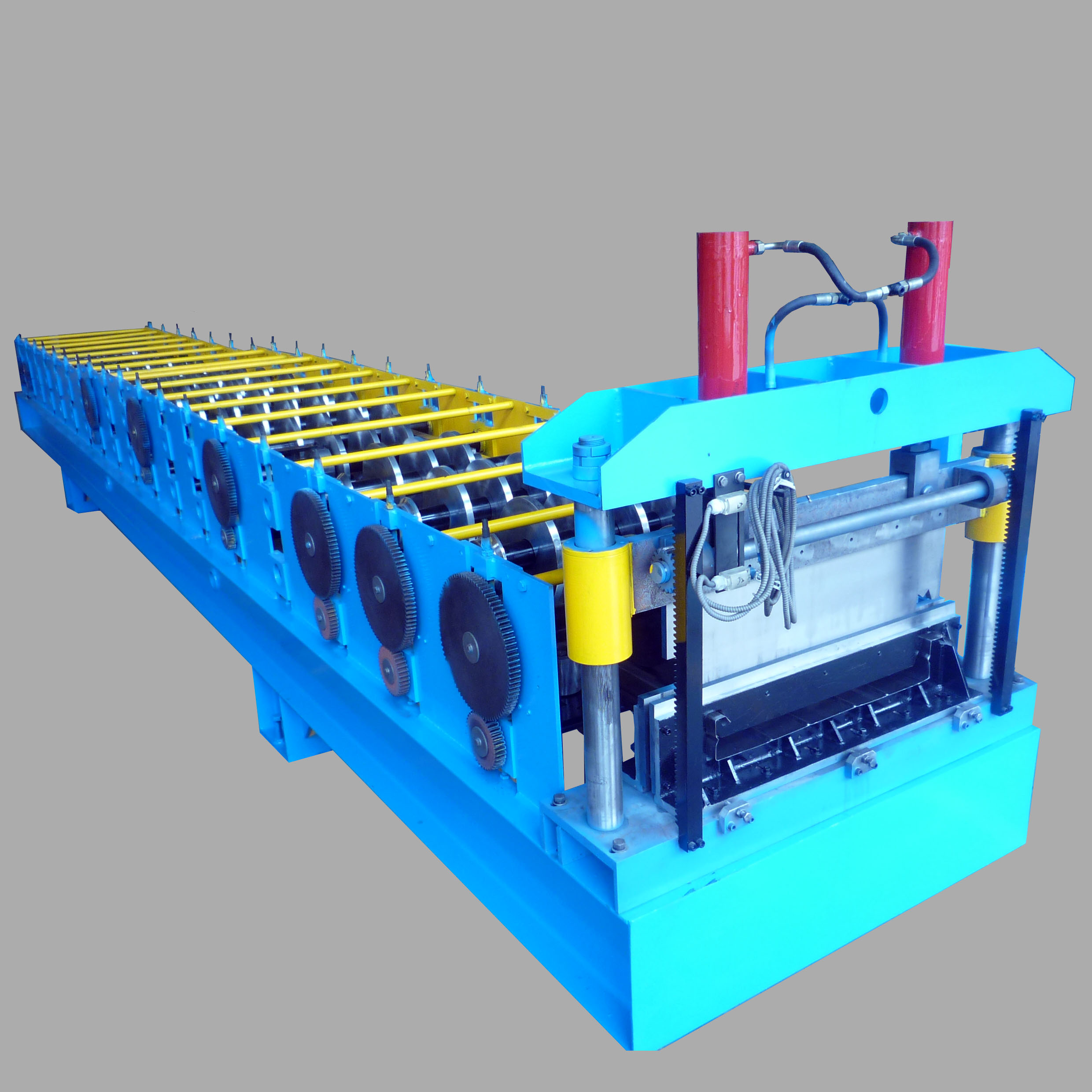
Figure 2 A physical model with the upper roll removed for illustration purposes, showing how the metal belt is formed as it passes through the different stations in the roll forming machine.
Because we live in a global market, reducing labor costs is the key. The quantity may vary depending on the application, part geometry, and market demand, but in typical cases, when the material content accounts for 60% to 90% of the total work cost, roll forming becomes competitive.
Many parts begin their life cycle on a bending machine and are finally produced on a roll forming machine. In fact, once the part volume exceeds 250,000 linear feet per year (note that this is in feet, not the number of parts), roll forming often becomes the most cost-effective option.
However, this number will vary with the complexity of the part. Only a few simple curved parts may require up to 500,000 linear feet per year for roll forming to make sense. Again, you may only have 10,000 linear feet a year, but because the parts are so complex, roll forming is still the cheapest option. If the rolling mill helps eliminate secondary welding or other operations, the number may be lower.
Know that these numbers are just generalizations. Consider a part that starts with a manual bending machine and then transfers to a robotic bending machine cell. The robot cell can meet the needs of customers, but the part itself may not take advantage of the bending cell. Offline simulation, smart material grading, flexible fixtures and automatic tool changes all create a system that can produce a wide variety of parts, and it is not limited to parts with continuous contours.
The decision to roll forming — or to use any other process, for that matter — actually boils down to making the most of the metal forming capabilities. Sometimes this requires questioning the status quo. Considering the state of the world, all future uncertainties, and the continuous advancement of manufacturing technology, questioning the status quo has become more important than ever.
FABRICATOR is the leading magazine for the North American metal forming and manufacturing industry. The magazine provides news, technical articles and case history, enabling manufacturers to do their jobs more efficiently. FABRICATOR has been serving the industry since 1970.
Now you can fully access the digital version of The FABRICATOR and easily access valuable industry resources.
Valuable industry resources can now be easily accessed through full access to the digital version of The Tube & Pipe Journal.
Enjoy full access to the digital edition of STAMPING Journal, which provides the latest technological advancements, best practices and industry news for the metal stamping market.
Enjoy full access to the digital version of The Additive Report and learn how to use additive manufacturing technology to increase operational efficiency and improve the bottom line.
Now you can fully access the digital version of The Fabricator en Español, easily accessing valuable industry resources.
Post time: Nov-23-2021